
Specifying Aerospace Roller Screw Electromechanical Actuators (EMAs): Mechanical Jamming Mitigation, Thermal Binding at -55°C, and Sourcing to SAE ARP5812 / RTCA DO-160G
Specify aerospace roller screw EMAs: assess jam isolation, thermal clearance and DO-160G evidence. Compare suppliers with an RFQ checklist and request a review.
Specifying aerospace roller screw electromechanical actuators (EMAs) starts with three questions: What happens if the screw jams, how does temperature change the loaded fits, and what evidence will the aircraft program accept? A catalogue force rating cannot answer these questions. Procurement should request a jam load-path drawing, a thermal tolerance budget, and a qualification evidence matrix before comparing price or mass.
Planetary and inverted roller screws are candidates for aircraft actuation where force, packaging and electrical integration justify them. Their suitability for a primary flight control depends on the installed architecture and certification basis; secondary mechanisms, eVTOL systems and military equipment can have different requirements.
Published / last content review: November 3, 2026.
Audience and scope: Global English-language sourcing guidance for mechanical engineers, systems engineers and technical buyers evaluating aerospace EMA concepts. The worked example screens an assumed -55°C to +125°C envelope; it does not establish a universal aerospace temperature range.
Evidence and limits: This is an analytical procurement guide, not a flight-qualified design or a report of hardware tests. Material coefficients below are assumed screening inputs. Obtain controlled material data, licensed standards and program-approved acceptance criteria before releasing hardware.
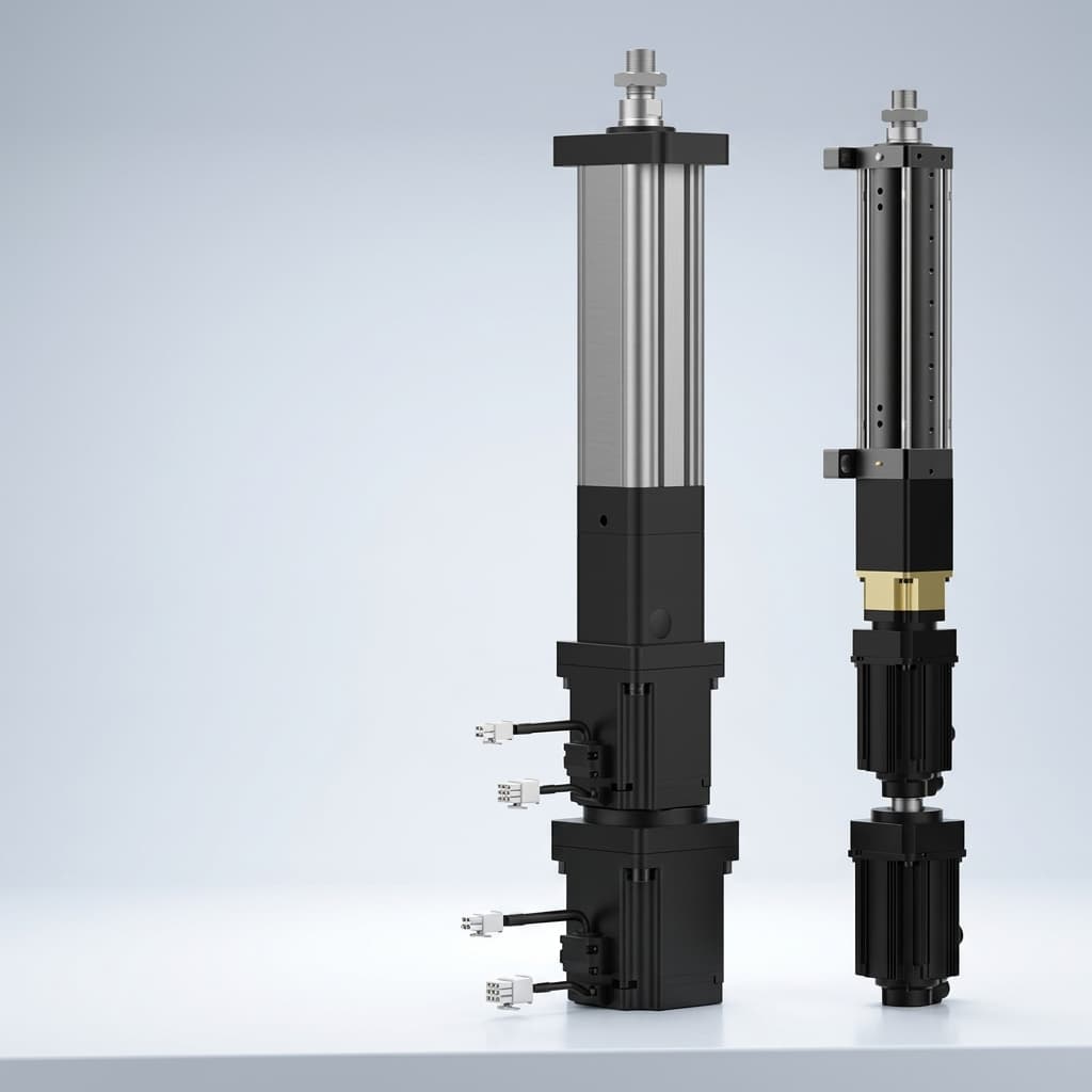
Cover image: Product illustration of servo cylinders, not evidence of an aerospace-qualified actuator. The schematic in Section 4 is conceptual.
Need to prepare a specification? Use the 10-point RFQ checklist or send your load, stroke and environmental requirements for a feasibility review.
1. Key Sourcing & Flight Control Decisions
Resolve these five decisions before issuing an aerospace roller screw EMA RFQ:
- Allocate the failure consequence at aircraft level. Identify the effect of a locked surface, loss of motion, unintended motion and a failed disconnect. Let the program safety assessment define the required mitigation rather than assigning a generic actuator failure-rate target.
- Define temperatures at the equipment. Include cold soak, motor self-heating, thermal gradients, storage, operating duty and minimum bus voltage. Evaluate the bearing and nut constraints as well as housing material.
- Specify the real motion spectrum. Include small-amplitude reversals, sustained loads, dwell and contamination. Select lubrication and any coating using representative endurance evidence.
- Draw the surviving load path after each jam. Two motor windings sharing one screw do not provide mechanical jam redundancy. An adjacent actuator cannot move a surface while a seized rigid connection still restrains it.
- Agree the evidence deliverables. SAE ARP5812 is a guide for preparing linear mechanical actuator specifications. RTCA DO-160 addresses environmental tests. Neither listing alone demonstrates airworthiness; state the agreed editions, applicable clauses and test configurations in the purchase specification.
For mechanism selection, see planetary versus inverted roller screw layouts.
2. The Mechanical Jamming Dilemma in Aerospace Flight Controls
2.1 Hydraulics vs. Electromechanical Failure Modes
Some hydraulic architectures can bypass a failed actuator so another actuator moves the surface. That behavior depends on the actual valves and failure; hydraulic equipment can also jam. A roller screw EMA has a solid mechanical transmission, and removing motor current does not free a seized nut, bearing or rod joint.
For a simplified series load path, axial stiffness can be screened with:
1 / K_total = 1 / K_screw + 1 / K_nut + 1 / K_bearing + 1 / K_housingUse the same stiffness units throughout and add attachment or surface flexibility where relevant. High stiffness supports positioning but can also transmit a jammed constraint directly to the airframe.
2.2 Safety Objectives Are Not Screw Ratings
FAA AC 25.1309-1B provides system-safety guidance for transport airplanes. Its quantitative guidance associates catastrophic failure conditions with average probability on the order of 10⁻⁹ per flight hour or less, together with qualitative requirements. This is not a catalogue reliability rating for an individual screw.
Important applicability boundary: Paragraph 1.2.2.4 excepts flight-control or pilot-control jams covered by 14 CFR 25.671(c)(3) from 25.1309(b). Have the certification team identify the applicable control-system jam requirements. Do not use a probability claim as the sole justification for a jammed flight control, or apply Part 25 guidance automatically to every eVTOL or military program.
3. Jam Mitigation Architectures and Health Monitoring
3.1 Architecture A: Mechanical Disconnect in the Jammed Load Path
A disconnect can isolate a seized assembly only if its release point removes the constraint between that jam and the output. A motor-side clutch cannot free a nut seized on the translating screw. Request a drawing that places each credible jam upstream or downstream of the release point.
Specify detection delay, release time, surface excursion, residual drag and the remaining actuator's authority. Demonstrate release under the worst signed load, side load, temperature and bus-voltage condition. Electromagnetic and one-shot release devices have different inspection, reset and inadvertent-release risks; no universal release time or mass penalty is assumed here.
3.2 Architecture B: Redundant Nut or Bypass Mechanism
A second nut is useful only if the mechanism provides a genuinely usable relative motion after the first nut locks. Two nuts constrained to the same shaft can share the same jam. Ask the supplier to demonstrate the kinematics, load transfer, available stroke, released-part retention and failure of the release feature itself. Do not accept a schematic of an extra nut as evidence of jam tolerance.
3.3 Architecture C: Parallel Actuation With Isolation
Parallel actuators can share normal loads, but each failed branch must release or otherwise stop restraining the surface. Define the surviving branch's force, speed and thermal duty after isolation. Check force fighting, common attachments, shared power, controls and contamination; duplication does not eliminate common-cause failures.
3.4 Supporting Measure: Prognostics & Health Monitoring (PHM)
Current, position, vibration and temperature trends can support fault detection and maintenance. Detection thresholds, nuisance trips and warning time need representative evidence. PHM does not itself create a surviving mechanical load path and should not be credited with a guaranteed warning before every jam.
4. Technical Architecture: Conceptual Aerospace EMA Schematic
The static diagram illustrates an inverted roller screw concept with shared mechanical parts, two motor lanes, position/health sensing and an output-side disconnect. Materials and bearings shown are options, not a released bill of materials. Release geometry, independent support paths and certification evidence are outside this conceptual drawing.
Diagram reading guide: The blue rollers transmit load between nut and screw. Both copper motor lanes use that shared mechanism. The red disconnect must isolate the relevant seized path; two electrical lanes alone cannot do so. No dimensions, release time or qualification status are implied.
5. Differential Thermal Binding at -55°C: The Physics of Cold Seizure
5.1 Thermal Clearance Budget Calculation
For a first screening calculation, model a freely expanding housing bore and an internal steel member at the same uniform temperature. With approximately equal initial diameters, the change in diametral clearance is:
Δc_d ≈ (α_housing − α_internal) × ΔT × D
c_d(T) ≈ c_d(assembly) + Δc_d
Here, α is the average linear coefficient of thermal expansion in K⁻¹, ΔT is the change from assembly temperature in K, and D is the fit diameter in mm. Positive clearance means a gap; negative clearance indicates interference in this simplified model. One-sided radial clearance changes by half the diametral value.
5.2 Reproducible Cold-Soak Example
Assumed inputs, not certified material data: assembly at +20°C; cold soak at -55°C; D = 80 mm; aluminum-like housing α = 23.4 × 10⁻⁶/K; steel-like internal member α = 10.5 × 10⁻⁶/K. Use supplier-certified values over the actual temperature interval for design release.
ΔT = -55 − 20 = -75 K
Δα = (23.4 − 10.5) × 10⁻⁶ = 12.9 × 10⁻⁶/K
Δc_d = 12.9 × 10⁻⁶ × (-75) × 80 = -0.0774 mm
     = -77.4 µm diametral = -38.7 µm one-sided radial
If an illustrative initial diametral gap were 100 µm, the free-expansion estimate would leave 22.6 µm. With a 50 µm initial gap, it would predict 27.4 µm interference. This difference shows why the initial fit and tolerances matter as much as the material choice.
Clearance screening is not a seizure prediction
The calculation does not establish roller preload, bearing load or motor torque. Press fits, housing compliance, thermal gradients, bearing geometry and lubrication change the result. Interference must be assessed in the full assembly; the 77.4 µm change alone cannot prove that the actuator jams or quantify a torque increase.
5.3 Compare Compensation Options
Using a titanium-like housing coefficient of 8.6 × 10⁻⁶/K with the same assumed steel gives a cold clearance change of +11.4 µm diametral. At +125°C, relative to assembly at +20°C, it gives -16.0 µm. A material change can reverse which temperature is critical; it does not guarantee a safe fit.
Evaluate compliant bearing supports, appropriate axial spring preload, radial flexures and revised fits according to the actual constraint direction. Verify loaded motion, breakaway torque, running torque and position error at both extremes, thermal transients and minimum voltage. Include seals, grease and motor heating in that test.
6. Tribology Under Autopilot Cruise Dither: False Brinelling & Coating Choices
6.1 Specify the Motion That the Lubricant Must Survive
Small oscillations under sustained load may limit lubricant replenishment and promote fretting or false-brinelling-type damage. Stroke amplitude alone cannot predict damage: contact geometry, load, lubricant supply, temperature and dwell all matter. Do not convert catalogue travel life into an oscillatory life guarantee without a representative test.
Send the supplier the reversal amplitude, frequency distribution, load history and temperature profile. Require an endurance method that measures torque growth, backlash, debris and contact condition against agreed limits, with inspection intervals and sample count recorded.
6.2 Coatings, Greases and Motion Strategies Are Test Variables
DLC or other coatings may be candidates, but adhesion, thickness, thread geometry, contact fatigue and grease compatibility need validation together. A low friction coefficient from a coupon test does not establish screw endurance.
MIL-PRF-23827 or MIL-PRF-81322 may be customer-specified grease references where applicable. They are not universal mandates for every roller screw. Identify the exact grease product and qualification status, cold torque, pressure/temperature compatibility, relubrication interval and seal compatibility. Any deliberate lubrication sweep must be approved against surface-motion and control-law constraints; do not add a fixed sweep to flight-control software from this guide.
7. Comparative Engineering Architecture Matrix
This is a qualitative RFQ comparison, not measured benchmark data. Compare complete installed systems at the same force, speed, stroke and duty. No architecture receives an assumed failure probability, force-density rating or certification approval.
| Candidate architecture | Jam or restraint to examine | Isolation question | Evidence to request |
|---|---|---|---|
| Hydraulic servo actuator | Valve, bearing or mechanical seizure | Does bypass cover the actual failure? | Bypass and residual-drag tests under representative load |
| Electro-hydrostatic actuator | Pump, valve, cylinder or attachment fault | Is the failed local hydraulic circuit bypassable? | Fault response and thermal-duty evidence |
| Single-path planetary roller screw EMA | Nut, bearing, screw or rod-joint jam | How is the seized output constraint removed? | Jam-location drawing and residual-load analysis |
| Inverted roller screw EMA | Shared rotating nut and support bearings | Can a release isolate the translating output? | Package, bearing-fit and release demonstrations |
| Parallel EMAs with disconnects | One branch locks against the surface | Can the surviving branch move the full load? | Loaded release, force-fight and common-cause assessment |
| Ball screw EMA | Ball track, return path or support seizure | Is a release or alternate motion path provided? | Matched-envelope load/life and jam comparison |
| Geared rotary actuator | Gear, bearing or output-joint seizure | Does the release bypass the actual seized stage? | Output-jam, stiffness and backlash evidence |
| Direct-drive linear actuator | Guide, bearing, attachment or foreign-object restraint | Are mechanical restraints and loss of power covered? | Force/thermal feasibility and guide-fault tests |
8. Material Selection & Metallurgy for Aerospace Envelopes
Select material and heat treatment from the complete load, manufacturing and environment case. The following six-component matrix defines evidence to request rather than prescribing unverified alloy/hardness combinations.
| Component | Selection question | Supplier evidence | Integration check |
|---|---|---|---|
| Main screw shaft | Contact fatigue versus core toughness and corrosion | Material certificate, heat-treatment records, hardness profile | Buckling, fatigue and finished-thread inspection |
| Planetary rollers | Compatible hardness, finish and optional coating | Surface integrity, coating adhesion and endurance results | Coating thickness included in thread fit |
| Internal nut | Raceway durability versus structural load capacity | Validated alloy/process route and dimensional report | Hoop deformation, preload and contact distribution |
| Housing and bearing seats | Mass, stiffness and differential thermal expansion | Material condition and temperature-dependent properties | Fit and preload at both temperature extremes |
| Timing elements | Wear, tooth loads and contamination tolerance | Geometry inspection and relevant endurance evidence | Synchronization and retained-debris behavior |
| Thrust bearings | Load spectrum, preload, lubrication and electrical effects | Bearing selection calculation and mounting instructions | Radial/axial restraint and hot/cold torque |
Specify traceability and non-destructive inspection methods, coverage and defect acceptance according to material, geometry and risk. Inspection reduces uncertainty; it does not prove the absence of every inclusion.
9. RTCA DO-160G Environmental Qualification Matrix
Use the contracted DO-160G edition/change and installation categories, or another revision agreed by the program. The RTCA overview explains the environmental-test scope; obtain the controlled standard for procedures. It does not substantiate the numeric test levels or acceptance limits of a particular actuator.
Each row below is a planning question. Category letters, levels, durations, operating modes and pass/fail criteria belong in the approved qualification test plan (QTP), with results in the qualification test report (QTR).
| DO-160G section | Installation input to define | Roller screw / EMA concern | Evidence to specify in the QTP |
|---|---|---|---|
| 4: Temperature and altitude | Operating, survival, short-time temperatures and pressure | Fits, cold lubricant torque, motor heating | Loaded motion and torque/temperature records at agreed conditions |
| 5: Temperature variation | Transition rate, gradients and dwell | Differential expansion and preload change | Position, torque and release checks through transients |
| 7: Operational shocks and crash safety | Installation loads, axes and retention requirements | Raceway damage, attachments and retained parts | Functional and structural results for the required test modes |
| 8: Vibration | Installation location, spectra, axes and duration | Fretting, synchronization and connector faults | Loaded response, wear and post-test functional inspection |
| 10: Waterproofness | Relevant water exposure and equipment installation | Ingress, seals and grease contamination | Ingress/functional acceptance defined for this test, separately from any IP rating |
| 11: Fluids susceptibility | Actual fluids, exposure conditions and materials | Seal, coating and lubricant compatibility | Material and functional changes against agreed limits |
| 20: Radio-frequency susceptibility | Controller, harness, grounding and applicable categories | Uncommanded motion or loss of feedback | Representative configuration and monitored actuator behavior |
| 21: Radio-frequency emissions | Equipment modes and installation emission limits | Interference from motor drive and cables | Conducted/radiated emission results; this is distinct from susceptibility |
Other sections, including humidity, electrical supply and lightning effects, may also apply. This is not a complete qualification plan. A QTR for another installation needs a documented applicability/gap assessment before reuse.
Request a feasibility and documentation review with your temperature profile, jam scenarios and required evidence. Identify existing reports, planned tests, cost and ownership separately in the quotation.
10. The 10-Point Aerospace EMA RFQ & Supplier Audit Checklist
- 1. Safety and scope: Record aircraft/system function, certification basis, failure conditions and the program-owned jam requirements.
- 2. Jam release: Identify each credible seized component, isolation point, required release time, residual drag and surviving authority. Verify under the specified signed loads and faults.
- 3. Thermal budget: Supply worst-case fits, tolerances, material properties and gradients across the defined operating/storage envelope; identify permitted preload or interference.
- 4. Dither endurance: Provide representative motion/load/temperature spectra, sample count, lubricant/coating details, inspections and explicit wear/torque/backlash criteria.
- 5. Materials and inspection: Agree traceability, heat-treatment evidence, appropriate NDT methods and defect limits for each critical part.
- 6. Electrical and feedback interfaces: Define supply extremes, channel independence, insulation requirements, sensor errors and failure responses; identify shared mechanical parts.
- 7. Dynamic performance: Supply installed stiffness, backlash and frequency-response data across load and temperature for the airframe team's aeroelastic assessment.
- 8. Qualification evidence: List standards, editions, applicable clauses/categories, QTP/QTR deliverables, test configuration and gaps in reused reports.
- 9. Cleanliness and sealing: Specify contamination limits, assembly controls, seal compatibility and maintenance assumptions justified by the actual mechanism.
- 10. Production acceptance: Agree serialized ATP records, inspection coverage, acceptance limits, configuration control and change notification before contract award.
For a reusable commercial handoff, see how to write a roller screw actuator RFQ.
11. Frequently Asked Questions (FAQ)
Can a ball screw EMA be used instead of a roller screw?
It can be a candidate when it meets the required load, envelope, life and motion profile. Compare matched systems and fault behavior. Neither mechanism is automatically suitable or unsuitable for a primary flight control, and a generic load-capacity multiplier cannot establish qualification.
How do one-shot and reusable disconnects compare?
Compare loaded release, inadvertent actuation, reset, inspection, device life and maintenance handling. Some reusable designs permit functional checks; a one-shot separation cannot be fully exercised without replacing the device. Timing, hold power and mass depend on design rather than a universal ranking.
Does a titanium housing solve thermal binding at -55°C?
It can reduce a particular mismatch, but it changes the sign and magnitude of fit movement. The Section 5 example predicts opening at cold and closing at hot for the assumed titanium/steel pair. Check bearings, supports, gradients and preload before selecting the housing.
Can motor-current monitoring replace mechanical jam isolation?
Monitoring can help identify degradation or a stall, but it cannot physically release a seized load path. Give it only the detection coverage demonstrated for the relevant faults, and assess what moves the surface after detection.
Is one grease specification mandatory for every aerospace roller screw?
No. The applicable program specification and validated component combination determine the lubricant. Ask for the exact product, compatibility evidence, cold-start torque and endurance results rather than accepting a specification number alone.
How should parallel actuators manage force fighting?
Define alignment, stiffness, sensing, load-sharing control and degraded modes together. Verify the resulting internal loads through reversals and after a channel fault. An unverified fixed percentage for load balance is not an acceptance criterion.
Which lead accuracy grade should the RFQ specify?
Start from allowable surface-position error, stroke, temperature and sensor/control budgets. State cumulative and local lead error in defined units, with the inspection method and reference temperature. If a supplier uses an accuracy class, identify its standard or catalogue definition rather than assuming a ball-screw class applies unchanged.
12. Engineering Consultation and Next Steps
A useful aerospace EMA specification connects the jam load path, thermal fit budget, representative endurance tests and qualification deliverables. Keep unknowns explicit so competing quotations include the same engineering and evidence scope.
Send an RFQ for a feasibility and technical sizing review with your force/speed/stroke profile, duty, available space, temperature limits and required documentation. Ask the supplier to identify demonstrated capabilities and any development or qualification work still required.
Explore aerospace EMA manufacturing and validation planning. A product illustration or consultation does not establish flight approval; acceptance remains tied to the program's controlled evidence.
13. Sources & References
- SAE International: ARP5812 — Actuators, Linear Mechanical, General Specification Guide. Official catalogue scope; reaffirmed January 9, 2025. Reference for preparing detailed specifications, including roller screw mechanisms. The catalogue description is not a clause-by-clause compliance assessment.
- RTCA: DO-160 — Environmental Conditions and Test Procedures for Airborne Equipment. Official overview of the environmental-test standard and supporting documents. This article discusses a DO-160G purchasing scope; confirm the contracted revision, changes and categories rather than treating G as a universal requirement or asserting it is the latest edition.
- FAA: AC 25.1309-1B — System Design and Analysis, issued August 30, 2024. Chapter 1 gives applicability and the flight-control-jam exception; Chapters 3–4 discuss failure conditions and safety objectives. FAA guidance is not an EASA publication or a qualification certificate for a component.
Public source scope checked November 3, 2026. No full-text review of the licensed SAE or RTCA standards, hardware testing or aerospace qualification claim is made. The thermal calculation uses declared assumptions and the matrices are editorial decision aids; replace them with program-controlled data and acceptance criteria for design release.
Author

More Posts
How to Audit and Select a Planetary Roller Screw Manufacturer: A 2026 Procurement Guide
Audit planetary roller screw manufacturers in 2026: verify load ratings, grinding control, testing proof, lead-time risk, TCO, and RFQ package readiness.
How to Prevent Premature Fatigue Failure in Roller Screw Actuators: An Engineering Guide
Learn why roller screw actuators fail prematurely, how spalling, brinelling, galling, misalignment, and lubrication gaps occur, and how to prevent them.
Specifying Roller Screw Actuators for Continuous Duty (S1) Applications: Thermal Management and Sizing Guide
Sizing roller screw actuators for S1 continuous duty: RMS force, thermal derating, cooling options, lubrication risks, and RFQ checks for engineers.