
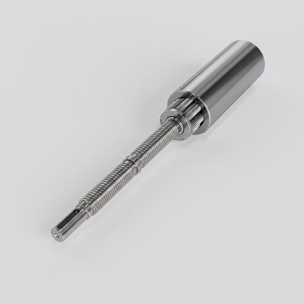
Specifying Linear Actuators for Humanoid Robots: Inverted Roller Screws, Reflected Inertia, False Brinelling, and Sourcing Protocols
Specifying linear actuators for humanoid robots? Compare lead, inertia, wear and life assumptions, then prepare an RFQ for your joint's load and duty cycle.
Specifying linear actuators for humanoid robots starts with joint geometry, a force–velocity duty cycle, and a mass and thermal budget. An inverted planetary roller screw (IPRS) can package a translating pushrod inside a rotating nut, but architecture alone does not establish impact tolerance, back-drivability, or operating life.
This guide gives mechanical engineers and procurement teams a way to compare transmissions, screen screw lead and inertia, and turn a gait load profile into a supplier qualification request. It focuses on engineering decisions that a peak-force catalog entry cannot resolve.
Content date / last reviewed: October 30, 2026. Region and language: Global, English. Scope: Preliminary selection for bipedal knee, hip and ankle linear actuators; the same questions can inform other mobile robot joints. Limits: The numerical examples are analytical assumptions, not measured robot performance or supplier test results. Validate linkage geometry, shocks, controls, lubrication and temperature on the intended assembly; this guide does not establish human-contact safety or certification.
Already have a joint load trace? Request an engineering review with your stroke, envelope and duty cycle.
1. Executive Sourcing Decisions: Sizing for Dynamic Locomotion
Before issuing an RFQ, resolve five architectural decisions:
- Separate fatigue, peak load and holding heat. A time-based RMS load can inform motor heating; it does not replace a travel-weighted screw fatigue calculation or a static overload check. Derive actuator force from joint torque and the position-dependent linkage moment arm, rather than equating ground reaction force with screw axial force.
- Keep the two inertia reference frames separate. With screw lead
landr = l / (2π), the rotary inertia reflected to the pushrod isJ_rotary / r², while the translating load reflected to the motor ism_load × r². A finer lead increases the former and reduces the latter. Section 4 gives the ideal model and its limits. - Test small oscillations as a separate wear case. Bearing failure terminology in ISO 15243:2017 helps distinguish damage modes. It does not prescribe a humanoid screw endurance test or guarantee that a coating prevents false brinelling.
- Choose inverted architecture from an assembly drawing. A rotating nut can improve packaging, but retracted length, anti-rotation guidance, support bearings, sealing and end attachments still consume space. Compare complete pin-to-pin envelopes at both stroke limits.
- Ask how the supplier defines life. ISO 281:2007 concerns rolling bearings and excludes wear, corrosion and electrical erosion from its life model. Do not treat it as a universal roller screw qualification standard. Require the screw manufacturer's rating basis, life exponent, reference travel and application limits.
2. Mechanical Architecture: Standard vs. Inverted Planetary Roller Screws in Robotics
In a common standard planetary roller screw arrangement, the screw shaft rotates and the nut translates. A rod-style actuator may use an additional output tube and guidance structure. Other drive arrangements exist, so an external motor and a doubled package length are not unavoidable properties of every standard roller screw.
In a common inverted arrangement, the nut rotates and the central output member translates. Integrating a frameless motor concentrically around the nut can reduce separate couplings and brackets. Roller retention, synchronization and the threaded contact geometry depend on the supplier's design; request a section drawing rather than inferring them from the word “inverted.”
Standard arrangement:
Motor -> rotating screw -> translating nut -> guided output member -> joint

Inverted arrangement:
Motor -> rotating nut -> roller contacts -> translating pushrod -> joint

Both need:
Thrust support + anti-rotation guidance + seals + stroke limits + load alignment
An inverted layout may place more actuator mass near a proximal attachment. Confirm this with the installed center of mass and joint motion, rather than assuming that a compact cylinder always reduces limb inertia. Likewise, ingress protection belongs to the tested complete assembly; a wiper seal alone does not establish an IP rating.
3. Architectural Comparison: Joint Actuation Technologies in Legged Robotics
This qualitative screening table identifies what to request from each supplier. It is not a measured ranking: size, reduction ratio, preload, cooling and linkage geometry can change the result.
| Transmission technology | Potential fit | Main selection trade-off | Evidence to request |
|---|---|---|---|
| Inverted planetary roller screw | Compact linear knee or ankle linkage | Integrated packaging versus rotating nut inertia, drag and service access | Complete envelope, rotor/nut inertia, reverse-drive torque and impact test |
| Standard planetary roller screw | High-load linear linkage with available axial space | Output guidance and motor location versus integration flexibility | Installed mass, screw support, buckling and speed limits |
| Precision ball screw | Linear joint where rated load and life are sufficient | Recirculation, preload and impact limits depend on the selected design | Static/dynamic ratings, reversal and shock qualification |
| Quasi-direct drive rotary | Joints prioritizing low reduction and torque transparency | Motor current, diameter and heat rejection for the required torque | Output inertia, continuous torque under installed cooling and torque bandwidth |
| Strain wave rotary | Compact high-ratio joint | Compliance, friction and overload limits | Lost motion, torsional stiffness, impact limit and duty-cycle life |
| Multi-stage planetary gearbox | Rotary joint with an established reduction requirement | Backlash, efficiency and reflected rotor inertia | Ratio, reverse-drive torque, output bearing load and fatigue limits |
| Electro-hydrostatic actuator | Application where hydraulic force and system integration are justified | Pump, fluid, sealing and thermal system complexity | Complete system mass, leakage, pressure transients and energy use |
| Direct drive rotary motor | Joint where available motor size can supply the torque | No reduction amplification; rotor inertia and copper loss remain | Rotor inertia, torque constant, current limit and mounted thermal test |
4. Dynamic Sizing & Kinematic Trade-offs: The Reflected Inertia Equation
4.1 The Physics of Reflected Inertia
For a rigid, backlash-free screw transmission, use the ideal kinetic-energy model below. Screw lead l is in metres per revolution, and r is in metres per radian.
r = l / (2π)
v = r × motor_angular_speed

Equivalent mass at the pushrod [kg]:
m_equivalent = m_load + J_rotary / r²

Equivalent inertia at the motor [kg·m²]:
J_equivalent = J_rotary + m_load × r²
J_rotary includes motor rotor, rotating nut or shaft, couplings and other rotating components referred to the same shaft. m_load is an equivalent translating mass for this simplified model; a limb's mass cannot simply be substituted without its linkage kinematics. These expressions follow from equality of translational and rotational kinetic energy; see the MIT classical mechanics teaching resource for the underlying mechanics.
Model friction, forward efficiency and reverse efficiency separately. A single efficiency multiplier in an inertia equation cannot describe both power-flow directions. At a robot joint, also transform through the local linkage Jacobian; stiffness, structural modes, control delay and current saturation affect contact response.
For the same rotary inertia, changing from a 2 mm to a 1 mm lead multiplies the rotary contribution to apparent pushrod mass by four. It does not establish a collision force or predict a bearing failure by itself.
4.2 Lead Optimization Matrix
Compare candidate leads against motor torque and speed, rather than selecting a universal “humanoid sweet spot.” The following arithmetic assumes a 0.10 m/s pushrod speed, 1,400 N axial load and an illustrative forward efficiency of 0.85. It excludes preload, seals, bearings and acceleration torque.
Motor speed [rpm] = 60 × |v| / l
Motor torque [N·m] = F × l / (2π × efficiency)

Lead 1.0 mm/rev: 6,000 rpm; 0.262 N·m
Lead 2.5 mm/rev: 2,400 rpm; 0.655 N·m
Lead 5.0 mm/rev: 1,200 rpm; 1.311 N·m
A larger lead reduces the ideal rotor contribution to reflected linear mass but increases torque for a given axial force. Request measured breakaway force and reverse-drive curves across preload, temperature and wear. Forward efficiency does not prove back-drivability, and back-drivability alone does not make a joint safe around people.
5. Technical Anatomy: Cross-Section of an Integrated Humanoid Linear Actuator
The conceptual schematic shows one possible concentric motor/nut arrangement, thrust support and sensor locations. It is an explanatory visual, not evidence of a particular product's dimensions, load rating or certified sealing performance.
Figure 1: Conceptual cross-section, not to scale or a manufacturing drawing. Architecture of an integrated inverted planetary roller screw actuator for humanoid knee and hip joints, featuring direct rotor-on-nut integration and dual-channel force/position feedback.
6. Tribological Survival: False Brinelling Under Micro-Oscillatory Balance Dithering
6.1 The Mechanism of Dither-Induced Wear
A standing robot can repeatedly reverse an actuator over a short travel range. Small-amplitude loaded motion may limit lubricant replenishment at rolling contacts and produce localized wear. Keep this distinct from true brinelling, which is permanent indentation from overload. Use ISO 15243:2017 for bearing damage classification; diagnosis of a roller screw requires inspection of the actual contacts and operating history.
Do not infer actuator oscillation frequency from a controller's sample rate. Record displacement amplitude, frequency, force, preload, lubricant, temperature and duration at the screw. Inspect both support bearings and screw contacts; an acceptable rolling-contact fatigue calculation cannot rule out short-stroke wear.
6.2 Three-Tier Engineering Countermeasures
- Lubricant qualification: Ask the screw and grease suppliers to agree a formulation, quantity and replenishment interval for the actual oscillation and temperature range. Specify measurable drag and wear acceptance criteria; base-oil chemistry alone is not a qualification.
- Surface treatment qualification: If a supplier proposes DLC or another coating, require coating thickness, adhesion, dimensional allowance and representative endurance data. Treat it as an option to validate, rather than a guarantee against damage under lubricant starvation.
- Controlled redistribution motion: A larger excursion may help redistribute lubricant, but schedule it only when joint motion is safe and compatible with balance control. Determine travel and interval experimentally; a generic automatic sweep can disturb a standing robot.
For an illustrative test request, a buyer could ask about ±50 µm at 30 Hz for 10 million oscillation cycles under a specified axial load. Define whether a cycle means a complete out-and-back motion, and agree sample count, inspection intervals, axial-play growth, drag change and reject criteria. This is a proposed test condition, not an ISO requirement or demonstrated service-life result.
7. Thermal Management & Dissipation in Uncooled Anthropomorphic Enclosures
Check motor copper loss during loaded standing as well as moving gait phases. Speed-dependent iron and inverter losses, screw friction, seal drag and bearing preload add heat during motion. Use the motor supplier's current and resistance conventions rather than mixing line current, phase current, peak current and RMS current.
For steady forward motoring, a preliminary screw friction estimate is P_loss = F × |v| × (1 / efficiency − 1). It excludes other losses and does not describe static holding heat or reverse-power operation. A high winding insulation rating is not a permissible housing, grease, magnet or human-contact temperature.
Steel screw components and an aluminum housing expand differently. Bearing arrangement and thermal gradients determine whether preload rises or falls. Request a thermal-mechanical analysis and a mounted duty-cycle test that records winding, housing and relevant bearing temperatures, drag and force derating at the specified ambient conditions.
8. Gait-Cycle Loading Profile & Dynamic Sizing Calculation (Worked Example: Bipedal Knee Joint)
8.1 Motion and Load Profile Breakdown
The following hypothetical axial-load spectrum demonstrates the arithmetic for a 70 kg robot design exercise. It is not a measured gait trace. The 4,200 N peak is an assumed screw load; it is not derived from body weight. Actual actuator force requires the joint torque, changing moment arm, inertial loads and load direction.
For a 2.5 mm/rev lead, a one-second cycle is simplified into four constant-load segments. The position column makes the assumed travel explicit; the 1 mm impact segment belongs to the chosen cycle and is not a universal heel-strike displacement.
| Phase | Time (s) | Axial load magnitude (N) | Position (mm) | Signed mean speed (m/s) | Absolute screw revolutions |
|---|---|---|---|---|---|
| Landing segment | 0.05 | 4,200 | 14 → 15 | 0.0200 | 0.4 |
| Stance extension | 0.35 | 1,400 | 15 → 45 | 0.0857 | 12.0 |
| Swing retraction | 0.30 | 350 | 45 → 10 | −0.1167 | 14.0 |
| Terminal extension | 0.30 | 200 | 10 → 14 | 0.0133 | 1.6 |
8.2 Calculation 1: Equivalent Dynamic Load
First obtain the supplier's screw life model. Only if it specifies an exponent of 3 and a one-million-revolution reference, the following cubic screening calculation applies. ISO 281 provides bearing-life context; it does not independently establish this model for a roller screw.
For segment i: revolutions_i = |travel_i| / lead
Total revolutions per cycle = 0.4 + 12 + 14 + 1.6 = 28.0

Weighted cubic sum [N³·rev]:
4,200³ × 0.4 + 1,400³ × 12 + 350³ × 14 + 200³ × 1.6
= 6.317625 × 10¹⁰

Equivalent load = (weighted cubic sum / 28.0)^(1/3)
                ≈ 1,312 N
If the supplier specifies another exponent p, use F_equivalent = (Σ(F_i^p × revolutions_i) / Σ(revolutions_i))^(1/p) with that supplier's rating basis. Evaluate load direction, preload and external moments as instructed by the supplier; dwell wear needs its own test.
The landing segment contributes about 46.9% of the assumed cubic sum while occupying 5% of the cycle time. That illustrates why travel and load weighting matter. It does not mean that sizing for the 1,400 N stance force would halve life: the calculated equivalent load here is lower than 1,400 N.
8.3 Calculation 2: Conditional L10 Fatigue-Life Screen
A target of 10 million one-second cycles gives 280 million screw revolutions and approximately 2,778 operating hours. Distance travelled by the robot cannot be inferred without a stride length. Under the conditional cubic model above:
C_required = F_equivalent × (target_revolutions / 1,000,000)^(1/3)
           ≈ 1,311.59 × 280^(1/3)
           ≈ 8,581 N = 8.58 kN
Basic L10 denotes a population fatigue-life rating at 90% reliability under the model's assumptions, rather than a guaranteed life for each assembly. It excludes failures such as lubricant depletion, fretting, seals, electronics and overload. Agree a separate endurance test with the supplier before selecting a production part.
8.4 Calculation 3: Static Safety Factor Check
An illustrative project screening factor of 2.0 gives C0_required = 2.0 × 4,200 = 8,400 N. This factor is not a universal humanoid requirement. Confirm how the supplier defines static rating and whether shock, combined loads and the required failure consequence demand a different margin.
Do not infer load ratings from screw diameter or roller count alone. Request the exact assembly's documented C and C0, output-rod buckling capacity, bearing ratings, allowable side load and mechanical stop loads. Passing these calculations is a shortlist decision, not approval of a robot joint.
Ready to compare a supplier proposal? Review the humanoid actuator product requirements alongside the RFQ checklist below.
9. The Humanoid Linear Actuator Procurement & RFQ Specification Checklist
Use these checkpoints to make quotations comparable and prototype acceptance reviewable:
- 1. Envelope and installed mass: Provide usable stroke, retracted and extended pin-to-pin distances, joint angles, cable clearance, attachments and the complete mass budget.
- 2. Load spectrum and kinematics: Supply time-stamped axial force, position and speed through the full gait cycle, the joint moment-arm calculation, shock cases and dwell periods.
- 3. Architecture and guidance: Request a section drawing identifying rotating parts, anti-rotation guidance, bearings, seals, lubrication access and end stops.
- 4. Lead, accuracy and back-driving: Compare candidate leads against motor speed and torque. State travel-error acceptance and measurement length explicitly; request measured breakaway force and reverse-drive behavior instead of assuming a grade or efficiency.
- 5. Dynamic and static rating basis: Require exact part ratings, life exponent, reference travel, load-direction rules, buckling limits and a project-approved overload margin.
- 6. Short-stroke wear test: Agree oscillation amplitude, frequency, axial load, preload, temperature, lubricant, sample count, duration and wear/drag rejection limits; qualify proposed coatings separately.
- 7. Motor and thermal limits: Specify DC bus range, peak-current duration, continuous phase-current convention, sensors, installed cooling path and temperature-based derating.
- 8. Position and force sensing: Define accuracy, resolution, bandwidth, calibration, drift, failure detection and mechanical mounting. Encoder bit depth alone is not joint accuracy.
- 9. Environment and friction: Specify operating temperature, contamination, ingress-test conditions, allowable seal/guide drag and service intervals for the complete actuator.
- 10. Supplier evidence and acceptance: Request traceable drawings and revision IDs, material/heat-treatment records, lead inspection, full-stroke drag traces, representative endurance data, sample quantities, lead times and agreed change-control rules.
10. Frequently Asked Questions (FAQ)
Why not use a miniature ball screw for humanoid knee actuators?
A ball screw can be a valid option when its rated load, packaging, reversal behavior and shock endurance meet the joint specification. Compare actual assemblies under the same load spectrum. A roller screw's distributed contacts may support a compact high-load design, but a universal percentage improvement or automatic ball-screw failure cannot be assumed.
What is the primary difference between standard and inverted roller screws in a robot leg?
In the arrangements described here, the standard screw rotates while its nut translates; the inverted nut rotates while its output member translates. Inverted packaging can support concentric motor integration. Confirm the installed length, bearings, guidance and mass distribution on the supplier drawing rather than assuming a fixed percentage reduction.
How does screw lead impact the humanoid robot's control response?
For fixed rotary inertia, its ideal reflected linear mass scales with 1 / lead². Finer lead increases this contribution while reducing motor torque for a given thrust. Select lead using required speed, motor limits, linkage geometry, friction and control-response tests; there is no generally optimal 2–3 mm lead for every robot.
What causes false brinelling, and how can we reduce the risk during standing?
Small-amplitude loaded oscillations can produce localized contact wear. Record the real screw motion and inspect the damage rather than diagnosing from controller frequency alone. Agree lubrication and endurance testing with the supplier; coatings and safe redistribution strokes are options to validate, not guaranteed remedies.
Can inverted roller screws be back-driven during compliance control?
Some assemblies can, but preload, lead, seals, lubricant, temperature and motor-drive state affect breakaway and reverse-drive behavior. Request measured curves across the intended operating range and an energy-management plan for regeneration. Back-drivability alone does not establish safe physical interaction.
How do engineers manage heat when the actuator is enclosed inside a robot leg?
Evaluate motor and inverter losses, screw friction, the mounting conduction path and the actual gait/standing duty cycle. Verify temperatures and force derating with the intended enclosure and ambient conditions. Confirm thermally induced preload changes instead of relying solely on a winding insulation class.
11. Engineering Consultation & RFQ Next Steps
For an initial engineering discussion, send your usable stroke, pin-to-pin envelope, target mass, joint geometry, force–velocity trace and holding-time requirements. Ask the supplier to identify assumptions, unavailable data, prototype deliverables and the tests needed before production approval. Motor integration, coatings, sensor options and achievable performance should be confirmed in the quotation for the selected assembly.
→ Request an engineering review for your humanoid linear actuator
→ Explore the roller screw actuator product portfolio
→ Review humanoid robot linear actuator requirements
12. Sources & Authoritative References
- ISO 15243:2017: Rolling bearings — Damage and failures — Terms, characteristics and causes. Primary reference for bearing failure terminology and classification. It is not a roller screw life guarantee or a robot-specific test protocol.
- ISO 281:2007: Rolling bearings — Dynamic load ratings and rating life. Primary reference for bearing rating-life scope and reliability context. Its public abstract excludes wear, corrosion and electrical erosion; obtain the screw manufacturer's model before applying a life equation.
- MIT OpenCourseWare: 8.01SC Classical Mechanics, Fall 2016. Foundational teaching reference for kinetic energy and rotational dynamics, underlying the ideal inertia transformation in Section 4; it does not validate actuator performance.
Reference review: October 30, 2026. The ISO catalog identities and public scopes were checked; no access to the full paid standards or physical actuator testing is claimed. The worked examples and RFQ criteria are preliminary engineering synthesis, not measured supplier capabilities.
Author

More Posts
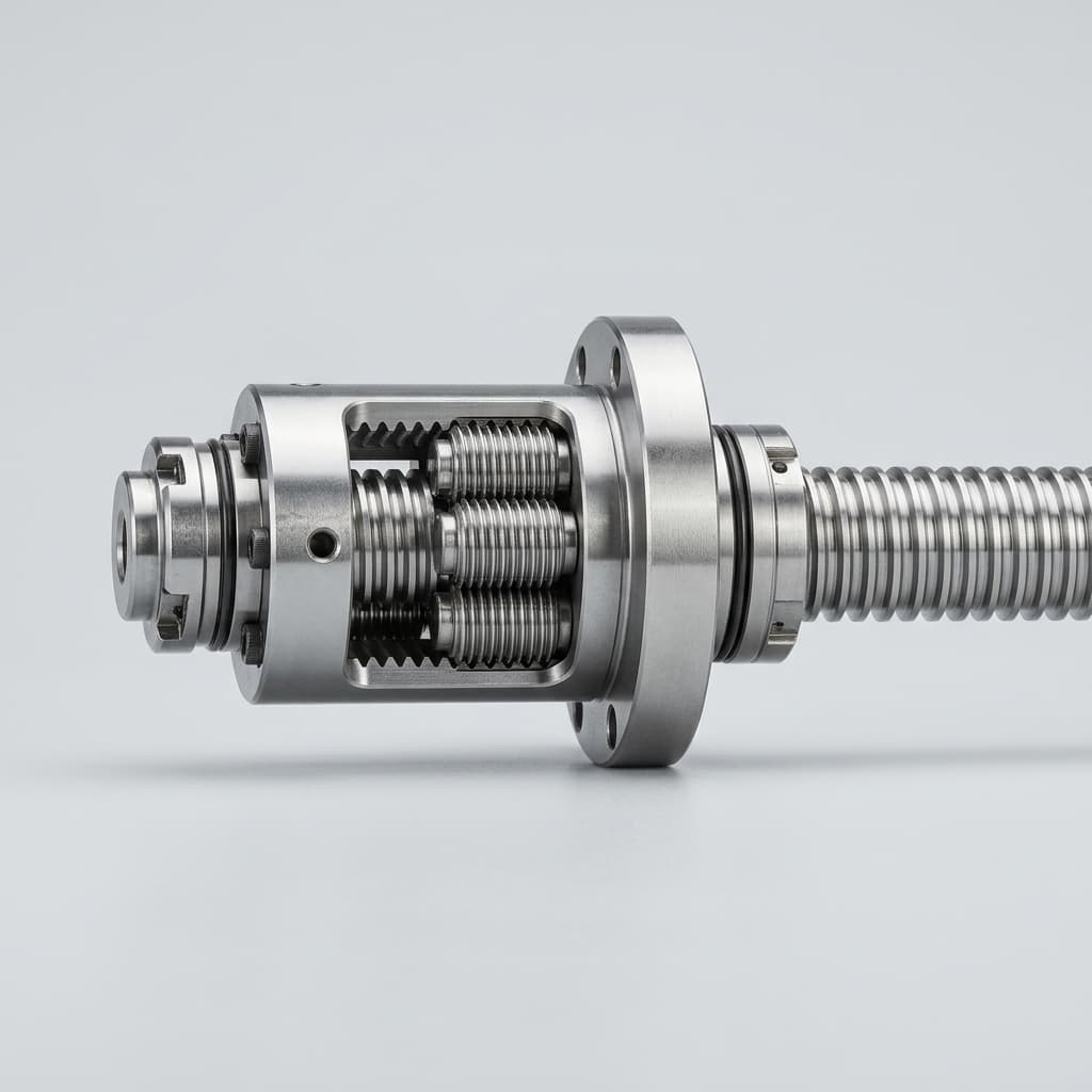
How to Audit and Select a Planetary Roller Screw Manufacturer: A 2026 Procurement Guide
Audit planetary roller screw manufacturers in 2026: verify load ratings, grinding control, testing proof, lead-time risk, TCO, and RFQ package readiness.
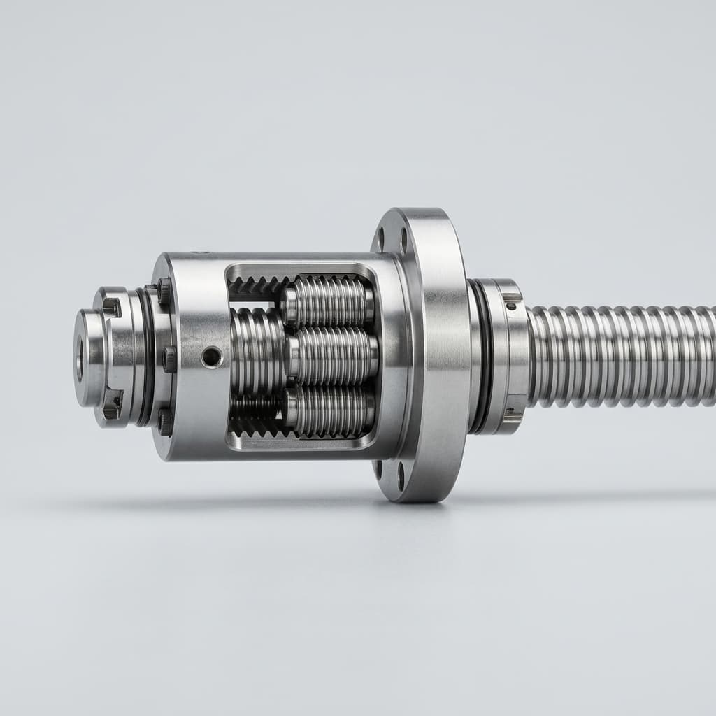
Roller Screw vs. Ball Screw: Which Linear Actuator is Right for Your Application?
A comprehensive engineering comparison of roller screws and ball screws, focusing on load capacity, lifespan, speed, and typical use cases in industrial automation.
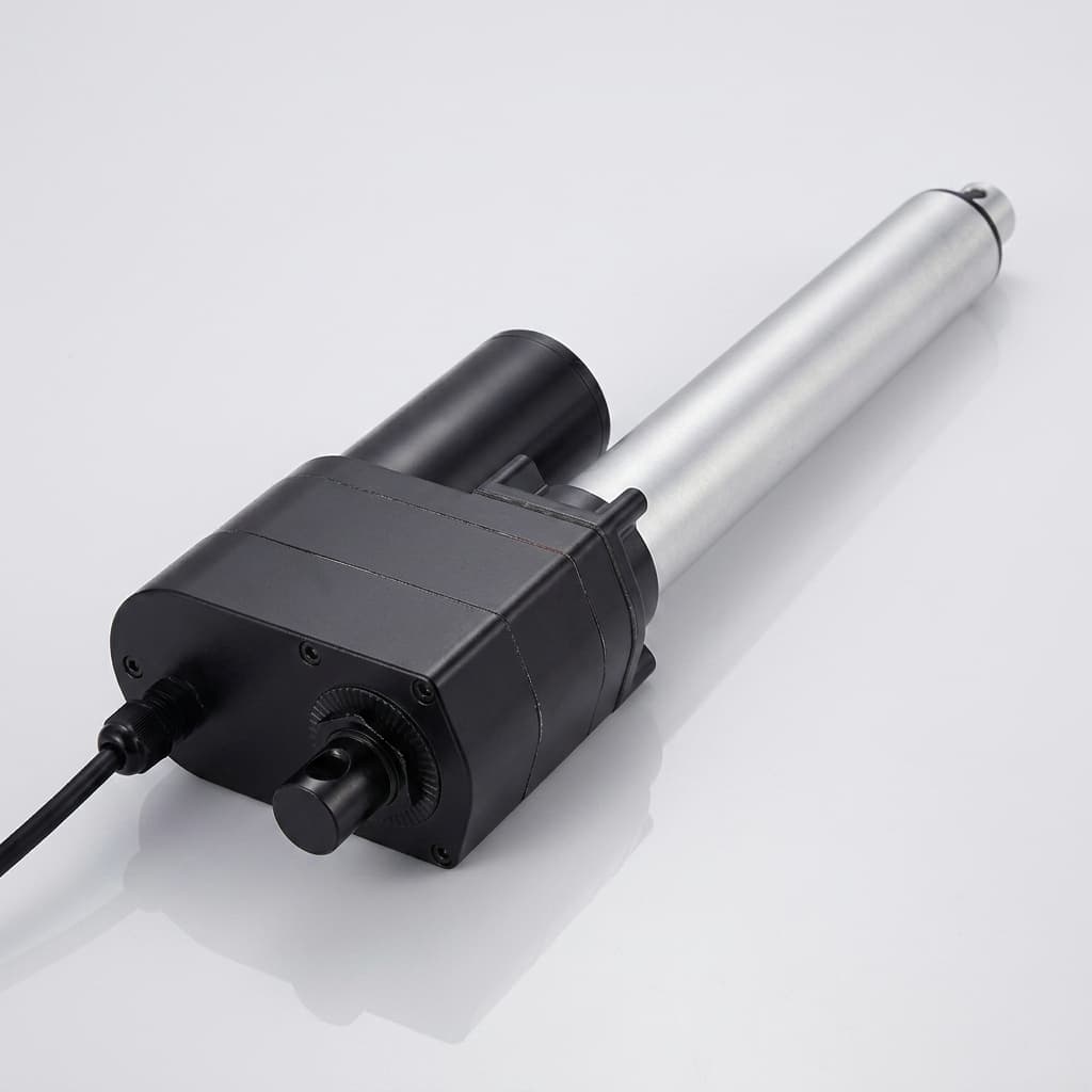
Specifying Roller Screw Actuators for Vertical Applications: Back-Driving Risks, Gravity Drop Prevention, and Holding Brake Sizing
Specify roller screw actuators for vertical applications: calculate holding brake torque, compare drop prevention options, and prepare your engineering RFQ.