
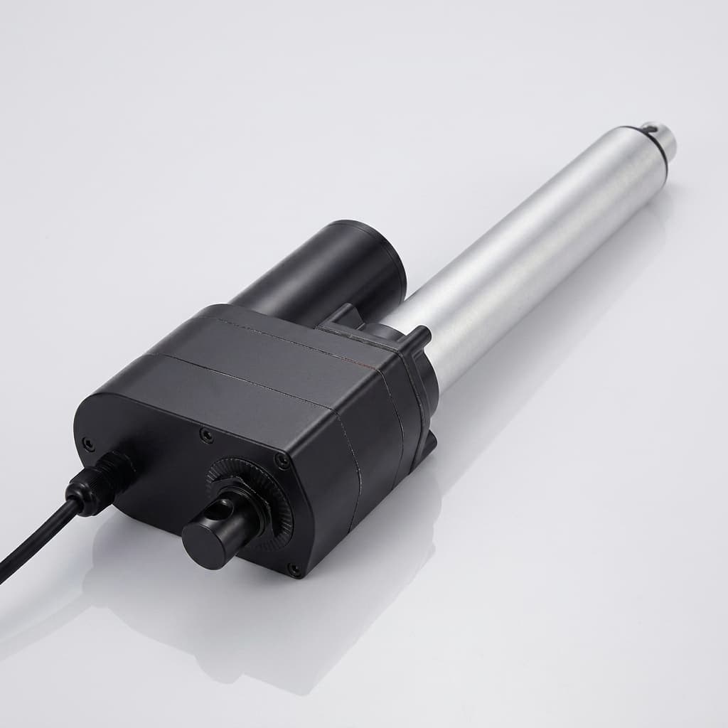
Specifying Roller Screw Actuators for Vertical Applications: Back-Driving Risks, Gravity Drop Prevention, and Holding Brake Sizing
Specify roller screw actuators for vertical applications: calculate holding brake torque, compare drop prevention options, and prepare your engineering RFQ.
Specifying roller screw actuators for vertical applications requires a load-holding design as well as a thrust rating. A gravity-loaded roller screw can back-drive when motor torque disappears. A hydraulic replacement project must therefore review how the original load-holding valves functioned and how the new electromechanical axis will support the load during stops, faults, and maintenance.
Treat the axis as back-drivable unless the screw and transmission suppliers establish otherwise for the actual lead, preload, lubrication, temperature, and wear conditions. Loss of motor torque can allow hazardous downward movement; its acceleration depends on reflected inertia, friction, and any counterbalance, so it is not necessarily free fall.
This guide gives mechanical engineers and procurement teams a reproducible holding-torque example, a comparison of arrest locations, and the evidence to request in an RFQ. It distinguishes static holding, dynamic emergency stopping, and personnel protection rather than treating a brake torque rating as proof of all three.
Content date / last reviewed: October 27, 2026. Scope: Global industrial machinery, vertical tooling slides, and hydraulic replacement projects using planetary or inverted roller screws. Limits: This is preliminary engineering guidance, not a machine safety validation or personnel-lift specification. Examples are hypothetical calculations, not measured actuator tests. Applicable standards, required performance level (PLr), and protective measures depend on the machine, access modes, and jurisdiction.
Preparing a specification? Use the RFQ checklist in section 10, then send your vertical-axis requirements for an engineering review.
1. Key Decisions for Sourcing & Engineering
- Do not assume self-locking: Obtain the selected screw's reverse-efficiency data or use a conservative lossless estimate for preliminary holding-torque sizing.
- Separate holding from stopping: A static holding rating does not establish permissible engagement speed, energy per emergency stop, or wear life.
- Specify brake timing: Motor torque must support the load while the brake engages during a controlled stop. Complete power loss needs a separately validated arrest response.
- Assess the entire load path: A motor brake cannot arrest a load after a downstream belt or coupling breaks. Required redundancy, diagnostics, and PLr come from the machine risk assessment; a component list alone establishes no PL.
DGUV FBHM-005, sections 3–4 and Tables 1–3 distinguishes access situations and protective measures, and explains why a successful static brake test does not prove dynamic stopping performance.
2. The Physics of Back-Driving in Roller Screw Actuators
To understand why vertical actuators drop, design engineers and buyers must evaluate the mechanical conversion between axial force and rotational torque.
2.1 Forward vs. Back-Driving Efficiency
In forward operation (motor driving linear load), input torque produces linear thrust:
F = 2π × T_in × η_f / lWhere:
- F = linear output force (N)
- T_in = torque at the screw input (N·m)
- l = screw lead (m per revolution)
- η_f = forward efficiency for the selected screw and operating point
When an external axial force acts on the actuator thrust rod (such as gravity pulling a 2,000 kg tooling head downward), the screw converts linear force back into rotational torque that spins the screw shaft and the motor rotor:
T_bd = F_axial × l × η_bd / (2π)Where:
- T_bd = back-driving torque at the screw shaft (N·m)
- F_axial = total downward axial load (N); for gravity alone, moving mass × g
- l = screw lead (m per revolution)
- η_bd = reverse efficiency, distinct from forward efficiency
These relations follow from work per revolution: linear work is F × l and rotary work is T × 2π. For a conservative preliminary estimate without verified loss data, use η_bd = 1 and do not credit seal drag or motor cogging. Add any downward process or spring force to the load case. If the brake is on the motor side of a reducer, convert torque to that shaft using its ratio and reverse efficiency; the calculation below assumes direct drive.
The screw lead trade-off: With load and reverse efficiency held constant, a 10 mm lead produces twice the back-driving torque of a 5 mm lead. A smaller lead also requires higher screw speed for the same linear velocity; recheck speed limits and drive sizing.
2.2 Worked Calculation: Gravity Back-Driving Torque
Consider a hypothetical direct-drive vertical tooling slide:
- Total moving mass, including payload, tooling, and moving actuator parts: 3,500 kg
- Gravitational acceleration: 9.81 m/s²
- Gravity load: 3,500 × 9.81 = 34,335 N (34.34 kN)
- Screw lead: 10 mm (0.010 m)
- Assumed reverse efficiency for sensitivity analysis: 0.85
Calculating torque at the screw shaft, which is also the brake shaft in this direct-drive example:
T_bd = 34,335 × 0.010 × 0.85 / (2π) ≈ 46.45 N·m
Lossless screening value = 34,335 × 0.010 / (2π) ≈ 54.65 N·m
A 45 N·m brake falls below both estimates before adding any design margin. Reject that preliminary selection; the motor's continuous torque rating does not compensate for inadequate brake torque when power is removed.
3. Holding Brake Sizing Methodology & Safety Factors
A brake must satisfy the load at its own shaft. Specify the guaranteed minimum holding torque under the expected temperature, wear, and contamination conditions, then assess dynamic stopping separately.
3.1 Static Design Margin (S_b)
For preliminary sizing, apply a documented design multiplier S_b to the worst-case back-driving torque. The example below uses S_b = 2.5 as an explicit project assumption, not a universal minimum from ISO or DGUV. Agree the final margin with the brake supplier and machine safety engineer.
Required minimum holding torque = T_bd × S_b| Design input | Required decision | Supplier evidence |
|---|---|---|
| Gravity and process load | Maximum net downward force | Mass breakdown and force cases |
| Lead and reverse efficiency | Torque generated at the screw | Exact screw data or lossless assumption |
| Brake location | Torque at the brake shaft | Ratio and transmission drawing |
| Temperature and wear | Guaranteed minimum holding torque | Derating and end-of-life limits |
| Emergency descent | Required stopping torque and energy | Dynamic ratings and allowable speed |
| Personnel access | Required protective architecture | Risk assessment and validation plan |
For the hypothetical slide, using the assumed reverse efficiency gives:
46.45 × 2.5 ≈ 116.1 N·m
Using the lossless screening value: 54.65 × 2.5 ≈ 136.6 N·m
The difference shows why an unverified efficiency assumption can undersize a brake. Use approximately 136.6 N·m as this example's preliminary requirement while supplier data are unavailable. It is not a final approved rating. A reducer can change shaft torque but also adds failure points; an external brake or load-side arrestor requires its own verification.
4. Architectural Comparison: Vertical Drop Prevention Technologies
Compare devices by where they interrupt the load path and what evidence is needed. These seven options are a procurement decision aid, not certified configurations or price estimates. Two brakes on one shaft can still share a downstream mechanical failure.
| Braking / arrest technology | Holding or stopping role | Remaining failure path | Evidence to request |
|---|---|---|---|
| Motor-integrated spring brake | Static holding; emergency use only within its rating | Belt, coupling, gearbox, and screw remain downstream | Minimum torque, response time, permitted emergency stops |
| Screw-shaft caliper brake | Holding; dynamic arrest only if rated | Screw, nut, bearings, and load attachments | Shaft torque, stop energy, mounting strength |
| Linear rod lock / tube clamp | Static clamping; some models permit dynamic arrest | Rod connection, clamp mounting, and frame | Rated force, rod surface requirements, dynamic-use approval |
| Guide rail brake | Load-side holding or stopping, model dependent | Rail anchorage and carriage attachment | Force and energy ratings, rail compatibility |
| Pneumatic / nitrogen counterbalance | Reduces net load; does not positively lock position | Pressure loss, leakage, hose or seal failure | Force over stroke, minimum pressure, failure response |
| Mechanical locking pin / support | Static support at a defined position | Pin engagement, shear capacity, and frame | Engagement confirmation and support load rating |
| Two independently controlled brakes | Two holding paths; stopping only if each is rated | Shared shafts, mountings, supply, or downstream parts | Independent test strategy and common-cause analysis |
For candidate actuator families, compare the roller screw actuator product range. Specify the required arrest location before requesting a brake option.
5. Technical Anatomy: Vertical Actuator Load Path & Safety Brakes
The schematic shows the motor-to-load path and an illustrative controlled-stop sequence. A rod clamp acts downstream of the coupling; a counterbalance is an optional load-reduction device, not a substitute for an arrestor. The drawing is conceptual and does not establish a safety category.
6. The "Gravity Sag" Trap and Safe Brake Control (SBC)
Even an adequately sized brake can allow downward movement if motor torque disappears before the brake develops holding force. Movement can also come from brake backlash and mechanical compliance. Define an allowable displacement for commissioning rather than assuming every axis has the same sag range.
This timing-related movement is often called gravity sag. Static holding torque, brake engagement time, and the drive's stop sequence are separate specification inputs.
6.1 Coil Inductance and Engagement Latency
For a spring-applied, electrically released brake, removing coil power starts engagement; full torque is not instantaneous. Request the maximum engagement time for the actual brake, switching circuit, suppression device, voltage, and temperature. Do not add generic coil and spring delay ranges to a datasheet value that already includes them.
An elementary unsupported-mass estimate is s = ½gt²: at 50 ms from rest, s is about 12.3 mm. This is a hypothetical free-fall reference, not a prediction for a screw-driven axis, whose rotational inertia and friction change the acceleration. Measure actual worst-case displacement during commissioning.
6.2 Controlled Stop, Restart, and Safe Brake Control
A preliminary controlled-stop sequence is:
- Decelerate: Bring the axis to the specified standstill condition under motor control.
- Command engagement: Remove brake release power while retaining load-supporting motor torque.
- Allow engagement: Use the supplier's maximum timing plus the validated control-chain allowance; check feedback where provided.
- Remove motor torque: Transfer load to the brake only after the specified holding condition is established.
- Restart: Establish load-supporting motor torque before brake release and allow the specified release time before motion.
SBC is a safety-related brake-control function; it does not itself prove mechanical holding capacity. A feature named “torque prove” also needs careful interpretation: in Rockwell's Kinetix example it checks motor phase current, rather than proving sufficient load-supporting torque. See MOTION-AT003C, pp. 3–4, 8–12, and 51 for product-specific limitations. Validate the selected drive and brake combination; a normal stop sequence cannot rely on continued motor torque during complete power loss.
7. Dynamic Energy Absorption in Emergency Deceleration (E-Stop)
An emergency stop during descent may require dynamic mechanical arrest if controlled motor deceleration is unavailable. Specify both the intended controlled stop and credible power-loss or drive-fault cases. An E-stop command does not automatically mean the holding brake should engage at full speed.
7.1 Kinetic Energy Equation for Vertical Stopping
For an uncounterbalanced descending load, a simplified available-energy estimate from the start of braking to standstill is:
E_available = ½mv² + mgs_stop + ½J_rotω²Where:
- m = total translating mass (kg)
- v = downward velocity when braking begins (m/s)
- s_stop = downward distance during braking (m)
- J_rot = rotating components' inertia reflected to the brake shaft (kg·m²), excluding the translating mass already counted in ½mv²
- ω = angular velocity at that same brake shaft (rad/s)
For the 3,500 kg example at an assumed 0.4 m/s and 0.020 m braking distance, translational energy is 280 J and gravitational work is 686.7 J: 966.7 J before adding rotating inertia. At 10 mm lead, direct-drive screw speed is about 251.3 rad/s. Brake delay adds travel and can raise engagement speed; evaluate that interval before using the equation.
This energy balance is not a stopping-distance solution. Allocate energy among the brake, drive regeneration, counterbalance, and losses using the actual system model. Check available dynamic torque and deceleration as well as energy per stop, total wear energy, repeat-stop interval, and allowed engagement speed.
RFQ requirement: Request the brake's documented dynamic-use limits and the supplier's stopping calculation. A static holding rating or a successful static brake test cannot establish emergency-stop capability.
8. Sizing Pneumatic & Nitrogen Counterbalance Systems
For continuous-duty vertical axes, a counterbalance can reduce gravity-related motor torque and dwell heating. Its effect on peak and RMS torque depends on the complete motion profile; upward torque does not follow a universal “double torque” rule.
8.1 Counterbalance Force and Failure Cases
For a parallel counterbalance, use the force available at each stroke position and the lowest credible pressure and temperature:
F_net_down = mg + F_process_down − F_counterbalanceAn illustrative 90% gravity offset reduces nominal gravity-related torque by 90%, with other inputs unchanged. This is not a universal sizing target and must not reduce the required arrest capacity unless the safety analysis justifies crediting the counterbalance. Assess pressure loss, leakage, force variation over stroke, and an empty-tool condition that could produce upward motion. Without justified credit, retain the full uncounterbalanced load case for the brake.
9. ISO 13849-1 & ISO 16092-2 Applicability for Procurement
The machine integrator must define safety functions and PLr, then validate the controls and mechanical load path. ISO 13849-1 addresses safety-related control systems; it does not assign a PL from brake torque alone. Ask for the applicable edition, reliability data, diagnostics, common-cause assessment, and fault response for the complete function.
ISO 16092-2:2019 covers mechanical presses, including its defined mechanical servo-press group. It is not a blanket standard for every electric cylinder, vertical slide, or hydraulic press. Confirm machine classification and applicable national requirements before specifying compliance.
9.1 Brake Testing and Access Conditions
Define the brake test interval, test load, dwell, permitted movement, and response to failure in the validated safety concept. Do not turn an example test torque or encoder-count threshold into a universal setting.
- Safe test position: Keep people outside the possible fall path and provide the protection needed if the tested brake fails.
- Independent verification: For multiple brakes, specify how each holding path is checked without masking a defective channel.
- Meaningful threshold: Convert encoder movement to actual load displacement using lead and ratio; account for backlash and compliance.
- Failure response: Inhibit hazardous operation and access until the load is secured and the fault corrected.
DGUV FBHM-005, Table 2 gives an eight-hour/shift maximum interval for its stated category-2 cyclic-test arrangement, with a guarded-access exception. That is context-specific guidance, not a universal 24-hour SBT mandate. Maintenance access also needs an appropriate support or locking method and energy isolation.
10. The Vertical Roller Screw Actuator Procurement & RFQ Checklist
Before issuing an RFQ or purchase order for a vertical electromechanical actuator, mechanical and procurement teams should audit suppliers against these critical checkpoints:
- Load cases: Include payload, tooling, moving actuator parts, process forces, and counterbalance-loss conditions.
- Motion profile: Supply stroke, maximum downward velocity, duty cycle, and allowable fault stopping distance.
- Torque calculation: Identify screw lead, reverse efficiency or lossless assumption, gear ratio, and brake shaft location.
- Holding margin: Document the agreed design factor and guaranteed minimum torque after applicable derating.
- Dynamic arrest: Obtain engagement-speed, torque, energy, wear, and repeat-stop limits for each relevant fault case.
- Load-path failures: Identify coupling, belt, screw, attachment, and common-cause failures; specify independent arrest where required.
- Controls and tests: Identify drive model/firmware, brake timing, SBC/SBT capabilities where required, diagnostics, and test acceptance criteria.
- Vertical lubrication: Obtain the actuator manufacturer's orientation approval, lubricant, delivery method, and service interval.
- Access and maintenance: Document PLr, guard behavior, mechanical support/locking, energy isolation, and validation responsibilities.
11. Frequently Asked Questions (FAQ)
Why did our previous hydraulic axis hold position after power loss?
Its circuit may have included load-holding check or counterbalance valves. Hydraulic cylinders are not inherently protected against descent: valve leakage, hose failure, and circuit design matter. Review the original schematic and safety function before replacing it with a roller screw actuator and brake.
Can we rely solely on the servo motor's internal holding brake for a vertical press?
Do not infer suitability from motor frame size, torque, or enclosure alone. The machine risk assessment and applicable press standard determine the protective measures. A motor brake leaves downstream transmission failures unarrested. Specify the needed independent holding paths, diagnostics, and maintenance support, and obtain validation for the complete machine function.
How does screw lead affect vertical back-driving risk?
At equal axial load and reverse efficiency, back-driving torque is proportional to lead: a 5 mm lead gives half the torque of a 10 mm lead. Real reverse efficiency can also change with geometry and operating conditions. A smaller lead requires more screw rpm for the same linear speed, so recheck the full selection.
What is the difference between Safe Brake Control (SBC) and Safe Torque Off (STO)?
STO prevents the drive from generating motor torque; it does not mechanically hold a gravity load. SBC provides safety-related brake actuation. The system still needs verified brake capacity, response timing, and the required diagnostics. Neither a brake output command nor SBC alone proves that the load is held.
How does vertical orientation affect roller screw lubrication life?
Orientation can affect oil distribution and lubricant retention, but a universal grease grade or baffle design is inappropriate. Ask the selected actuator manufacturer to approve vertical operation and specify lubricant compatibility, delivery points, relubrication quantity, and interval for the actual speed, load, temperature, and contamination conditions.
How often should vertical holding brakes be tested or replaced?
Use the validated test plan and the brake manufacturer's wear, emergency-stop, and service limits. Calendar intervals alone do not establish remaining capacity. Record dynamic stops and follow the manufacturer's inspection or replacement criteria before returning a faulted axis to service. Section 9 explains the scope of the cited DGUV cyclic-test interval.
12. Conclusion & Engineering Consultation
Specify a vertical roller screw actuator around the complete load path: gravity and process loads, torque at the brake shaft, guaranteed holding capacity, dynamic arrest limits, controls, and access conditions. Keep the assumptions in the calculation visible so the supplier can challenge them before an order is placed.
The worked example and comparison tables support preliminary selection. Final stopping distance, safety performance, and service intervals require supplier evidence and machine-level validation; they cannot be guaranteed by this article.
Engineering a high-tonnage vertical axis or replacing a vertical hydraulic cylinder?
Send the moving mass, stroke, speed profile, mounting arrangement, drive model, required holding and stopping behavior, and personnel-access conditions. Ask the quotation to identify which brake and arrest options are available, their documented limits, and who validates the completed system.
→ Contact Our Engineering Team for a Vertical Sizing Review & RFQ
→ Explore High-Load Planetary Roller Screw Actuator Solutions
13. Sources & References
- DGUV: FBHM-005: Gravity-loaded axes (Vertical axes), August 2021. Sections 3–4 and Tables 1–3 address access-dependent protective measures, cyclic testing, and the distinction between static holding and emergency stopping. This is German technical guidance, not a global compliance certificate.
- Rockwell Automation: Vertical Load and Holding Brake Management, MOTION-AT003C-EN-P, April 2019. Pages 3–4, 8–12, and 51 explain holding-brake limitations, product-dependent response times, and the limits of torque proving. Its Kinetix settings are not universal drive parameters.
- ISO: ISO 16092-2:2019 — Machine tools safety — Presses — Part 2: Safety requirement for mechanical presses. The public scope identifies the covered mechanical press groups and exclusions; it does not establish compliance of a particular roller screw actuator.
Sources checked October 27, 2026. Numerical examples and procurement comparison criteria are this article's engineering synthesis, not supplier test results or quotations of standard-mandated design factors. Recheck source editions and component data when finalizing the machine specification.
Author

More Posts
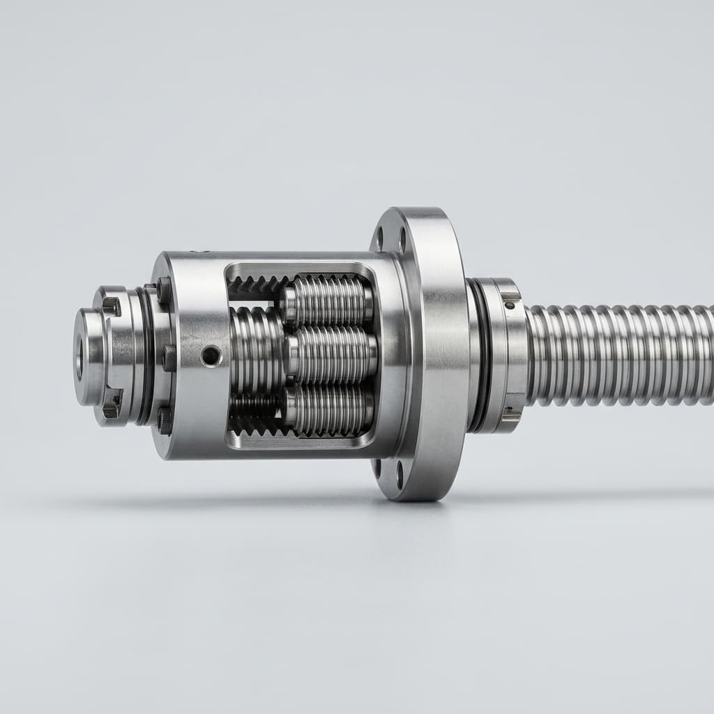
How to Audit and Select a Planetary Roller Screw Manufacturer: A 2026 Procurement Guide
Audit planetary roller screw manufacturers in 2026: verify load ratings, grinding control, testing proof, lead-time risk, TCO, and RFQ package readiness.
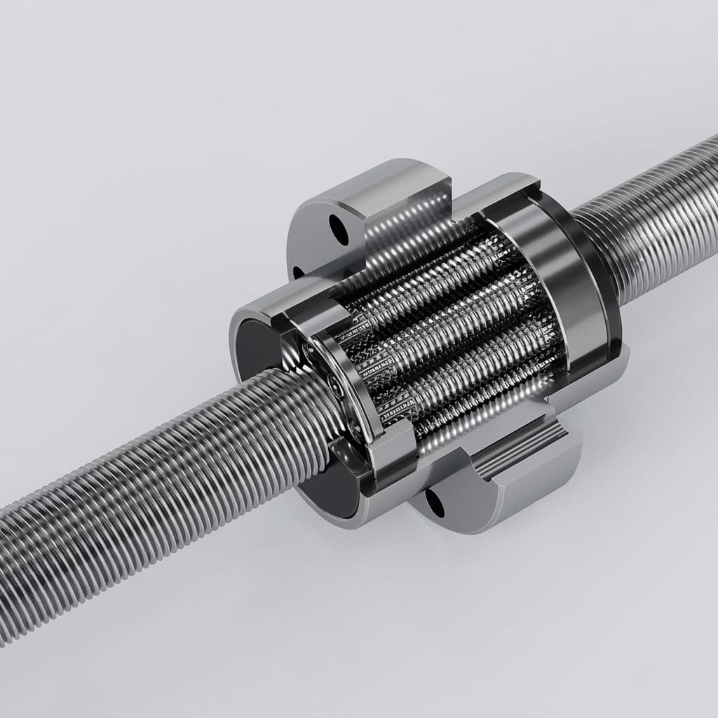
Specifying Roller Screw Actuators for Continuous Duty (S1) Applications: Thermal Management and Sizing Guide
Sizing roller screw actuators for S1 continuous duty: RMS force, thermal derating, cooling options, lubrication risks, and RFQ checks for engineers.
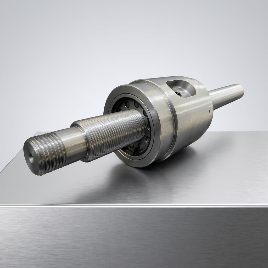
Planetary Roller Screw Actuators in Servo Press Applications: Sizing and Selection
Learn why planetary roller screw actuators are commonly specified for servo press machines. We cover force distribution, shock tolerance, and key sizing parameters for precision joining and forming.